Vent
The vent diameter has been derived from the product brochure of the Avalon Opus Ceramique loudspeaker. The diameter of the vent is 5 cm. Hence the vent area F = 20 cm2. Other parameters of the C2220-T6 that are needed for dimensioning the vent are Qts = 0.272, Vas = 144l, Vb = 47.5l, and fs = 20.4Hz. Following the calculations on the summary page, we find a fb = 26.5Hz, and a vent length of 13.3cm. For reasons of availability, we take a vent with a length of 15cm. Measurements show that the resulting vent frequency is at 11Hz.Vented systems explained
There is much confusion about the way vented speakers operates. Friedemann Hausdorf of Visaton explains the operation of vented speakers by a nice analogy of a spring and a mass (for more info see the German Elektor article - German only). For the non-German speaking reader, I'll translate some of the highlights.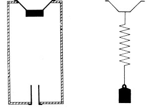
[Elektor, 1986]
In this analogy, the air in the vent is associated with a mass, the air in the enclosure is associated with a spring, and the speaker acting as an active source to move the air in the enclosure is associated with some active means (e.g. a hand) that presses or pulls a spring. The speaker moves the air in the enclosure, which on its turn moves the air in the vent. The movement of the air in the vent is delayed in time. The amount of delay and movement depends on the frequency (or the speed with which the spring is moved):
1. Very low frequency. Both the back of the speaker and the air in the vent move almost in phase, just like the mass and spring would move in phase with the hand. Hence outside the speaker enclosure the front of the speaker and the outlet of the vent are out of phase. In this operating range the source is not dampened anymore, and care must be taken to limit the excitation.
2. Very high frequency. The air in the vent is hardly/not reacting to the fast movement of the speaker, just like the mass would hardly react to very fast movement of a hand. Hence, there is hardly any output of the vent.
3. At the port frequency fb. The air in the vent will react very strongly to the movement of the speaker (like the mass and the spring). The speaker/vent combination (or spring/mass combination) have a slight delay with respect to each other. Outside the speaker, a phase shift of 90 degrees can be observed (because movement is the derivative of acceleration).
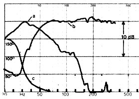
This is illustrated by the following figure, where (b) is the output of the loudspeaker, (a) the output of the vent, and (c) the phase difference between woofer and vent opening.
[Elektor, 1986]
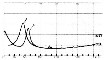
Applying a vent to an enclosure, will shift the impedance peak upwards, as shown by the following curve, and introduce a second impedance peak due to the resonance of the vent.
[Elektor, 1986]
The tuning of the length and diameter of the reflex pipe depends on the properties of the active source (amount of air it moves - Vas, and its resonance frequency - fs), and the volume of the enclosure (Vb). One can compare this with blowing air on the opening of a bottle. The frequency depends on the amount of air in the bottle, and the shape of the opening.
In the same article Hausdorf provides experimental results about vented designs that hardly seem to find some consensus.
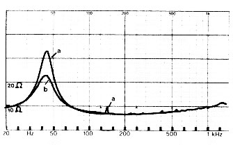
First of all, many people say that hardly any filling should be applied to vented speaker designs. This is true for the area around the vent, as the operation of the vent depends on the acceleration of air. But in other parts of the enclosure, filling might help to reduce standing waves (see the peak at 150Hz in the following figure) and lower the impedance peak of the speaker.
[Elektor, 1986]
A second observation discusses the difference between sealed enclosures and vented enclosures. It is true that vented enclosures have a somewhat worse impulse response, due to the phase shift of the vent. It is often forgotten however that awoofer in a sealed enclosure is used around its resonance frequency, and also has a phase shift. The differences in phase shift between a sealed and vented enclosure is shown by the following figure, questioning the audibility of this difference at these low frequencies and in living room conditions. In Hausdorf's article, impulse response curves are shown in living room conditions, hardly showing any visible difference in the impulse response.
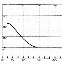
[Elektor, 1986]
Last but not least, Hausdorf shows that an increase of the length of the vent results in a better impulse response (from b to a in the following figure), approaching the response of a sealed enclosure. Hence the vent length can be used to trade-off more bass versus better impulse response. The use of very short vents results in "boom-boxes", a phenomenon where vented speakers have been and are still associated with. This is unjustified, because properly dimensioned vented speakers have a comparable impulse response in practical situations.
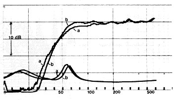
[Elektor, 1986]
Last but not least, vented speakers offer advantages in term of linearity. As the speaker only has to move a bit to excite the vent, it operates in its linear region for a larger total output.
Rule of thumb calculations
Hausdorf suggests to calculate the properties of a sealed speaker box first, and then to determine the resonance of the vented speaker and vent dimensions. The procedure is:1. Calculate resonance for a sealed speaker:
2. Calculate Q for sealed speaker:
3. Calculate the resonance for the vented speaker. According to the original literature about vented speaker design (from Thiel), the resonance of the port fb needs to be situated at the frequency associated with the minimum of this new impedance curve. According to Thiel, fb = 0.7 x fc. Scientists are still debating the exact position of fb compared to fc. Hausforf has good experience with the following values:
A. When Qtc > 0.7, fb needs to be far from fc to obtain a good impulse response. In his case he finds good results for fb = 0.6 to 0.7 x fc.
B. When Qtc < 0.7, fb and fc should be closer together to obtain some efficiency. In his case he finds good results for fb = 0.75 x fc.
4. Calculate the length of the vent in cm (F is the area of the vent in cm^2):
Other calculations
There is a nice quick-and-dirty calculation tool on this website.Furthermore, there is the table based on Thiel's work published in the AES.
Using this figure, the resulting vent length is about 10cm.
Efficiency of bass reflex systems
Many people think that bass reflex systems are more efficient, because the port "adds energy". As the port is a "passive element", this cannot be the case. In September 2002, Dick Pierce posted an article in rec.audio.tech, explaining the whole principle very well:An optimally designed reflex is 3dB more efficient than a sealed box for the same enclosure size and bandwidth because it CAN be. Why, because the driver ITSELF is 3 dB more efficient.
How do you make a driver more efficient? Couple of ways: you can reduce the moving mass, reduce the DC resistance, or increase the stength of the motor system (we’ll assume we’re keeping the driver size the same). But, assume we’ve designed a maximum- efficiency closed box system (Qt=1.2) and we increase the efficiency of the driver. What happens?
Well, if we reduce the mass of the driver, the resonant frequency goes up and we no longer have the same cutoff frequency. That’s not good (not for our gedanken, at any rate).
We could decrease the DC resistance or increase the Bl product. Doing both of these, while increasing the efficiency, lowers the Qt of the system AND raises the cutoff frequency.
What we’re leading to here is if we design a system with a driver that has a stronger magnet/voice coil system, and is thus INHERENTLY more efficient, in a selaed box (again, everything else being equal), we’ll end up with an INHERENTLY more efficient system, BUT with a non-optimum bandwidth/enclosure size relation in the direction of being overdamped.
So, what we CAN do is introduce a secondary aperture that allows the enclosure to act itself as a tuned system whose PRIMARY purpose is to provide the mojority of the output in the region where the output of the driver directly is falling off due to the increased damping from the motor system.
Imagine, if you will, the response of our overdamped system: drooping well above resonance, significantly down at resonance and gradually approaching it’s ultimate rolloff rate. Now, imagine a secondary source of radiation that essentially fills in the missing system output in this region: that secondary system is the port/enclosure resonant system.
The 3 dB gain in efficiency comes NOT from the fact that the port is there: it comes from the fact that the driver ITSELF is 3 dB more efficient to begin with. If you take a csealed box speaker and punch a hole in it, what happens to the efficiency? (hint: nothing!) If you take a reflex system and plug the port, what happens to the efficiency? (second hint: nothing)
What, you may ask, defines efficiency? It’s defined, essentially, as the ratio of the total acoustical power out over the bandwidth of the speaker divided by the electrical power in. Notice the qualifier: “over the bandwidth of the speaker.” To put it in more precise terms, the “reference efficiency” of the system is defined as its electro-acoustic conversion efficiency “over the piston band of the speaker,” i.e. the region above the system resonance and below the point where the wavelength starts to approach the size of the driver.
Given this definition, and knowledge of the fact that the port conly contribute output over a narrow range of frequencies around the enclosure resonance Fb, it should become clear why the port itself is not what’s making the system 3 dB more efficient (especially considering that over the frequency range where the port output is greatest, the driver’s output is minimized). What the port is doing is filling in the otherwise reduced response a more efficient and over-damped system would have.
Secondarily, the reduction of driver motion due to the port has other benefits: decreased distortion at that range where the excursion-dependent distprtion would otherwise be the greatest and increased mechanical power limits.
next ->