Electrical Stage [14-11-2006]
About the Milestones filter design
The Milestones filter is in development. Filter design is a complex matter, requiring a careful trade-off between acoustical, mechanical and electrical behavior, and with many interactions with the environment. This page gives a short description of the most recent filter. For those who are interested, the filter logbook will present a chronological tour through past filter designs.Circuit
The Milestones filter circuit and its response is given in the figures below (click on the pictures for an enlargement).
The component types are as follows. All capacitors are Audyn Cap Plus, except C2a, C2b, who are ordinary Audyn Caps. All inductors are Intertechnik Copper Foil inductors. There doesn't exist a 0.12mH version, so I bought a 0.15mH, and modified it to a 0.12mH one. Finally, all resistors are MOX-10 resistors.
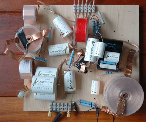
I have a photo of an intermediate filter, showing some different components (e.g. a Tritec inductor):
The following sections will discuss the properties of this filter. A more detailed explanation can be found on the filter explanation page. The sonic properties of the filter are described at the main page of this project.
Acoustic response
Basically the filter circuit realizes a 2nd order acoustic Linkwitz-Riley response between woofer and midrange, and a 4th-order acoustic Linkwitz-Riley response between midrange and tweeter:
The following picture shows the fit of theoretical 2nd and 4th order Linkwitz-Riley curves:
The crossover frequencies are roughly at 250Hz and 3.1kHz. A response dip in the range of 2 – 4 kHz has been created on purpose, to compensate for some harshness as experienced with a flat response curve. People, who are more confident about a flat response, can leave out R7, and lower the value of C7 to 3.3uF, though it makes the sound a bit “harder”, and affects the depth of the spatial field.
As the units have been measured in an anechoic room, they will give a bit more output in a normal listening room, and as a consequence the bass is attenuated a bit. The remaining on-axis response is quite flat. There is a +1dB peak at 500Hz, a -2dB dip at 800Hz, and a +2B peak at 12 kHz, all caused by the separate response of the single units. There are some small discrepancies around 3.5kHz and 8kHz, caused by tweeter diffractions, and above 10kHz the tweeter starts to bundle.
Linkwitz-Riley implies that the acoustic phase is aligned at crossover. I took care the phase is aligned over a very wide operating range, to make the speaker less sensitive to the exact positioning of the listener:
This is confirmed by looking at the midrange in reversed phase, giving steep dips at the crossover points:
The acoustical phase alignment also results in a good overall response at different angles horizontally:
Electrical response
The electrical power response shows baffle step compensation is applied, with more power output supplied to the low frequency range:
It is built up of voltage and current as follows:
The impedance curve looks as follows:
The impedance dips a little bit below 4 Ohm. The speaker has been tested with a low-power single-ended triode amplifier, and despite its moderate efficiency of 85dB/W, the speakers seems to go loud enough without the need for impedance compensation for a typical European living room situation. It can play very loud, without a hint of "scratching distortion". The bass, though less tight than with my own Ayre AX-7 amplifier, still sounds solid and punchy with a zero-feedback tube amplifier.
Filter measurements
I have measured the speaker to check the consistency of the filter and the simulation results. Because I have made these measurements in living room conditions, reverberations have affected most curves. Nevertheless, important conclusions can been drawn from these measurements.First of all, besides significant reflections from the floor and ceiling below 200 Hz, overall the response curve at 1.80 m looks very similar to the simulated response.
A sanity check measurement at 1-meter distance indeed shows that this peak in the response due to reflections moves up in frequency, and a dip occurs at 150Hz.
This response remains very stable over different angles (15 and 30 degrees at 1 meter), also in line with the simulations.
The anti-phase measurements (window width 2 ms to avoid reflections inside the measurement) show that the phase alignment is very well.
The near-field curves of the units look pretty OK, where the tweeter response falls down due to the close measurement distance, and the low-frequency measurements of the woofer are influenced a little bit by background noise. As the microphone measurement distance differs for each units due to the grills, I've adjusted the tweeter measurements with 10dB.
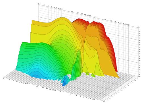
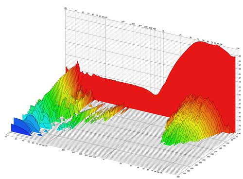
I’ve also measured the nearfield waterfall behavior of the filtered units. The “magazine measurement” of 20/30dB deep of each unit looks pretty OK (e.g. for the midrange uni (5ms, 20dB deep)t:
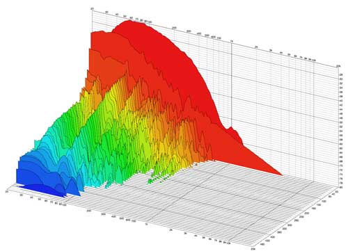
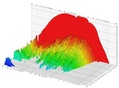
If you start to look deeper into the measurement (50dB), you can see a lot of resonances show up:
Filter implementation
I’ve spend quite some time in experimenting with components. With some financial support of interested people, I've bought some good quality components (IT copper foil inductors, Audyn Cap Plus MKP capacitors), and based on the result I've tweaked the filter a bit.My conclusion is that copper foil inductors and certain types of MKP capacitors yield good results, and contribute to a timbre that combines transparency with energy over the whole frequency range, together with good pinpointing and a wide and deep 3D image.
To do
What does it take to get to the final filter? Well, basically it is a matter of tuning R1, R3 and R11. I’m also experimenting with an RC compensation circuit in parallel with the woofer. It is a matter of trading off transparency for fullness. For this I have to judge a lot of recordings, before I’m able to finalize the filter. It will also be a matter of personal priorities, so my suggestion is that you experiment for your own situation and preference as well. I expect to finish the filter before the end of the year. It is my goal build this filter inside the cabinets. With all these big capacitors and copper foil inductors that will be quite some challenge!next -->