Backgrounds
This page gives some limited technical background of the circuitry used in the original Classic 25. The background information will mainlyexis of links to other web pages, because most background material is explained already very well by other references.
For some general info about tubes, see the first 21 pages of the RCA receiving tube manual. For a good introduction to tubes, I would recommend the book Fundamentals of Radio-Valve Technique from DeKeth. It's a classic, which is very easy to read.
Input
The design starts with input connectors at the back of the cabinet. A flat-cable is used to direct the input signals to the switches on the front of the cabinet.The switches are mounted on a PCB. The first switch selects between CD, tuner, aux1 and aux2. The second switch selects between the signal selected from the first switch, or from a tape recorder (providing the possibility to monitor a recording directly).
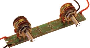
After the switches, a balance and volume control follow (see the picture below). These are 100kOhm each. The volume pot is an open Noble type.
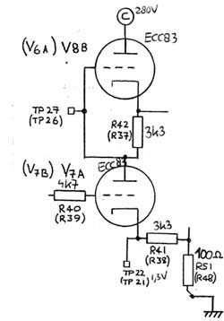
SRPP stage
The first stage in the Classic is an SRPP stage, shown below. It consists of the two triodes of an ECC83 tube. For an explanation how an SRPP works, see the Tube CAD articles called SRPP decoded, and SRPP once again.From the 1.3V voltage at TP22, it can be deducted that the quiesent current is 0.4mA, and Vak is 139V. The amplification of the first stage, without feedback, is 53,5x.
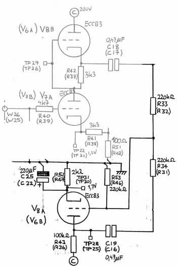
Phase splitter
The goal of the phase splitter is to make a180 degrees out of phase copy of the input signal. Such an out of phase signal is needed for the push-pull output stage.To get an idea of different kind of phase splitter, have a look at the following phase splitters pdf file.The phase-splitter in the Classic is a floating para-phase phase splitter, as shown below.
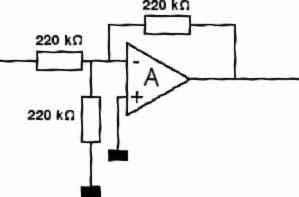
If drawn a bit differently, the circuitry around the inverting tube would look as follows (thanks to Peter van Willenswaard):
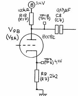
Driver stage
The driver stage (2 are there) amplifies the signals, and provides low impedance output for the EL-34s inside the output stage. The driver stage is a so-called common cathode stage. Some info about common cathode stages can be found at common cathode amplifiers, simulations with common cathode circuits, and the loadline pages on Steve Bench's web pages. Information about determining resistor values can be found at TubeCAD.From the voltages, it can be deducted that the quiescent current is 2mA, Vak = 100V, A = 10.8x.
Push-pull ultra-linear output stage
See the Williamson amplifier for more info about push-pull ultra-linear output stages. See this article published in Audio Engineering of 1953 for an explanation of push-pull.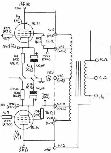
next->